Introduction
Computers and computer programs are all about solving problems. To solve problems, we need to understand the idea of logic – what happens when something and/or something else happens.
To see how this works inside a computer’s architecture, we can draw logic circuits using logic gates.
In this lesson, we’ll learn about:
- What logic gates are
- Logic diagrams using AND
- Logic diagrams using OR
- Logic diagrams using NOT

What Logic Gates Are
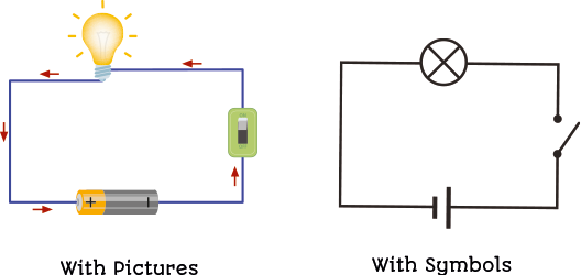
If you look at the lights in your classroom, they can be either ON or OFF.
Your lights are controlled by a switch on the wall. If the switch is ON, the lights are ON. If the switch is OFF, the lights are OFF. There is no such concept as ‘sort of on’.
This works by closing an electrical circuit, allowing current to flow to the lights, when you press a switch.

What Logic Gates Are
If you turn off a light, you are opening a switch, meaning electrical current cannot flow to the light.
Much like your light switch, computers are made up of switches too.
Inside your computer, in your RAM memory, and inside your CPU, there are billions of tiny switches that are storing 1’s and 0’s by being either open or shut. That’s how your computer works.
Logic gates represent how these switches are used in computers.
By combining these logic gates, we create circuits, just like the circuits in your computer, which allow you to store a file or play a video game, all by turning on and off switches.
Logic Diagrams Using AND
The first logic gate we’ll learn is an AND gate. This looks like Figure 2 below.
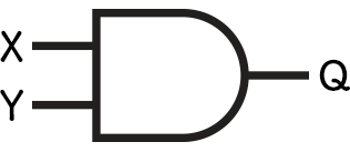
In the image above, you can see that this AND gate takes two inputs and gives one output.
When BOTH of this logic gate’s inputs are 1 (remember, computers only use 1s and 0s), it will output a 1. Otherwise, it will output a 0.
It can be beneficial to think of this in terms of switches & lightbulbs.
Logic Diagrams Using AND
Imagine you had two switches in a line, as shown in Figure 3.
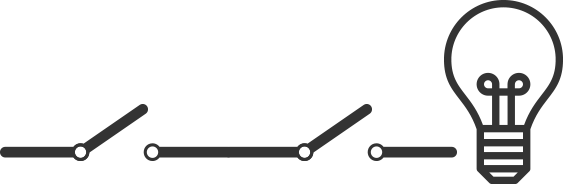
Both switches are open (turned off), so no power can reach the light bulb, so the light bulb is turned off.
As we’ve learnt, your computer is just made up of switches, when they’re open, they represent a 0, and when they’re closed, they represent a 1.
So here we have two 0’s, leading to no electricity reaching our lightbulb (which we can also think of as a 0).
Logic Diagrams Using AND
Now, let’s say we close ONE of the switches.

One switch is now closed (turned on), so power passes through it. This represents a binary 1.
However, the second switch is open, so the power cannot reach the lightbulb, and so it’s still turned off.
Logic Diagrams Using AND
Finally, we close BOTH of the switches.

Both switches are closed, representing binary 1s.
This means power can reach our lightbulb and it turns on, representing an output of binary 1.
Logic Diagrams Using OR
Let’s see how this looks using the switches & lightbulb example.
The next type of logic gate is an OR gate. This looks like Figure 6 below.
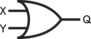
In the image above, you can see that this OR gate takes two inputs and gives one output.
When either of this logic gate’s inputs is 1, it will output a 1. Otherwise, it will output a 0.

Logic Diagrams Using OR
Instead of having two switches in a line, we have two separate lines with switches on them, as shown in Figure 7.
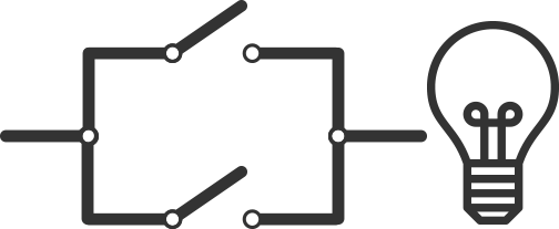
Both switches are open (representing 0’s), so no power can reach the light bulb.
This means the light bulb is turned off (representing a 0).
Logic Diagrams Using OR
Now let’s say we close ONE of the switches.

One switch is now closed, and so it passes power through it.
This represents a binary 1.
The second switch is open, but the power can still reach the lightbulb, so it’s now turned on, representing an output of binary 1.
Logic Diagrams Using OR
Finally, we close BOTH of the switches.

Both switches are closed, representing binary 1s.
This means power can still reach our lightbulb, and it turns on, representing an output of binary 1.
Logic Diagrams Using NOT
Another common logic gate is the NOT gate. This looks like Figure 10 below.
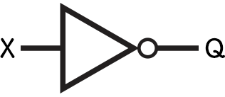
This differs from the other types of gate diagrams as it only has one input and one output.
When a NOT gate has an input of 1, it gives an output of 0. When it has an input of 0, it gives an output of 1.
We can’t really represent this with our light bulb analogy. It would be like someone had wired the light switch the wrong way so that when you turned it OFF, the lights went ON.

Lesson Summary
Electrical switches can either be ON or OFF, corresponding to a 1 or a 0.
An AND gate returns a 1 if both its inputs are a 1. Otherwise, it returns a 0.
An OR gate returns a 1 if either of its inputs is a 1. Otherwise, it returns a 0.
A NOT gate flips the input, so a 1 becomes a 0 and vice versa.