Introduction
We have seen how logic circuits can be drawn as diagrams with inputs and outputs, and we can use truth tables to map out the range of possible results from these circuits.
However, we can also combine a series of logic gates to produce more complex circuits.
This allows us to solve problems and identify logical structures in how a computer works.
In this lesson, we’ll learn about:
- Combining logic gates to produce simple circuits.
- Applying logical diagrams & operators in truth tables to solve problems.

Producing Simple Circuits
We can start to put logic gates together to make larger circuits.
Each circuit can be represented as a Boolean expression, which will always start with an output, usually called Q.
To solve these, start with the brackets on the inside and work outwards.
Let’s work through three different expressions:
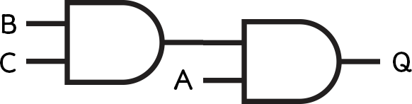
- Q = A AND (B AND C)
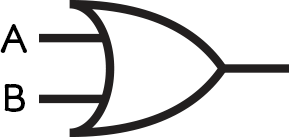
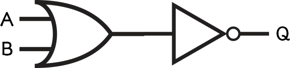
- Q = NOT (A OR B)
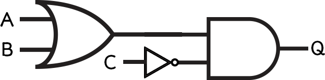
- Q = (A OR B) AND NOT C

Worked Example 1
Step 1
Start with the brackets. This is the “B AND C” part.

Step 2
Add the outer expression; this is the “A AND” part.
Worked Example 2
Step 1
Start with the brackets. This is the “A OR B” part.
Step 2
Add the outer expression. This is the “NOT” part.
Worked Example 3
Step 1
Start with the brackets. This is the “A + B” part.
Step 2
Add the outer expression. This is the “. C” part.
Solving Problems
We have seen how we can use Boolean algebra to represent some circuits.
We can build up truth tables to show all the inputs and all the possible outputs for any circuit.
We can then use this to work out which combination of inputs will give us a TRUE output.
The way to do this is to start small and build up your truth table column by column.
Solving Problems
In your exam, you might need to complete a truth table for a given Boolean expression or draw the circuit diagram for a Boolean expression and then plot the truth table.
In order to solve this, you can follow some very simple steps:
- Build your inputs
- Check to see if any of your inputs have been NOTed
- Build your expressions from your initial inputs
- Look at the final output
Let’s now work through three example Boolean expressions.
Worked Example 1
Step 1: Build your inputs
We have two inputs, A and NOT B. So, we need 4 rows.
| A | B | Q |
|---|---|---|
| 1 | 1 | |
| 1 | 0 | |
| 0 | 1 | |
| 0 | 0 |
Step 2: Check to see if any of your inputs have been NOTed
Yes – B has been NOTed, so add a column for NOT B.
| A | B | NOT B | Q |
|---|---|---|---|
| 1 | 1 | 0 | |
| 1 | 0 | 1 | |
| 0 | 1 | 0 | |
| 0 | 0 | 1 |
Notice how all we have done is flip the B column values.
Worked Example 1
Step 3: Build your expressions from your initial inputs
Now, we need to add the expression by comparing the A column and the NOT B column.
As it is an AND gate, the output will be true if both inputs are true.
| A | B | NOT B | Q |
|---|---|---|---|
| 1 | 1 | 0 | 0 |
| 1 | 0 | 1 | 1 |
| 0 | 1 | 0 | 0 |
| 0 | 0 | 1 | 0 |
Worked Example 1
Step 4: Look at the final output
We can see that there is only one possible input to this circuit that gives a TRUE output.
When A = 1 and B = 0.
Worked Example 2
Step 1: Build your inputs
First, we have three inputs, so let’s see the truth table outline. We should have 8 rows this time.
| A | B | C | Q |
|---|---|---|---|
| 1 | 1 | 1 | |
| 1 | 1 | 0 | |
| 1 | 0 | 1 | |
| 1 | 0 | 0 | |
| 0 | 1 | 1 | |
| 0 | 1 | 0 | |
| 0 | 0 | 1 | |
| 0 | 0 | 0 |
Step 2: Check to see if any of your inputs have been NOTed
They haven’t so we can skip this step.
Worked Example 2
Step 3: Build your expressions from your initial inputs
First, we have A OR B – ignore C for the moment.
| A | B | C | A OR B | Q |
|---|---|---|---|---|
| 1 | 1 | 1 | 1 | |
| 1 | 1 | 0 | 1 | |
| 1 | 0 | 1 | 1 | |
| 1 | 0 | 0 | 1 | |
| 0 | 1 | 1 | 1 | |
| 0 | 1 | 0 | 1 | |
| 0 | 0 | 1 | 0 | |
| 0 | 0 | 0 | 0 |
Worked Example 2
Now, we can add the AND C part.
Remember it’s AND – so it’s where we have a 1 in the A OR B column, AND we have a 1 in the C column.
| A | B | C | A OR B | Q |
|---|---|---|---|---|
| 1 | 1 | 1 | 1 | 1 |
| 1 | 1 | 0 | 1 | 0 |
| 1 | 0 | 1 | 1 | 1 |
| 1 | 0 | 0 | 1 | 0 |
| 0 | 1 | 1 | 1 | 1 |
| 0 | 1 | 0 | 1 | 0 |
| 0 | 0 | 1 | 0 | 0 |
| 0 | 0 | 0 | 0 | 0 |
Worked Example 2
Step 4: Look at the final output
The following table shows the combinations of A, B, and C that give us a TRUE output.
| A | B | C |
|---|---|---|
| 1 | 1 | 1 |
| 1 | 0 | 1 |
| 0 | 1 | 1 |
Worked Example 3
Step 1: Build your inputs
First, we have 3 inputs, so let’s look at the truth table outline. We should have 8 rows.
| A | B | C | Q |
|---|---|---|---|
| 1 | 1 | 1 | |
| 1 | 1 | 0 | |
| 1 | 0 | 1 | |
| 1 | 0 | 0 | |
| 0 | 1 | 1 | |
| 0 | 1 | 0 | |
| 0 | 0 | 1 | |
| 0 | 0 | 0 |
Worked Example 3
Step 2: Check to see if any of your inputs have been NOTed
Yes – we have NOT B and NOT C, so we add these columns.
| A | B | C | NOT B | NOT C | Q |
|---|---|---|---|---|---|
| 1 | 1 | 1 | 0 | 0 | |
| 1 | 1 | 0 | 0 | 1 | |
| 1 | 0 | 1 | 1 | 0 | |
| 1 | 0 | 0 | 1 | 1 | |
| 0 | 1 | 1 | 0 | 0 | |
| 0 | 1 | 0 | 0 | 1 | |
| 0 | 0 | 1 | 1 | 0 | |
| 0 | 0 | 0 | 1 | 1 |
Worked Example 3
Step 3: Build your expressions from your initial inputs
First, we have A AND NOT B, so we add this column – again, the output is TRUE when both inputs are TRUE, as it is an AND gate.
| A | B | C | NOT B | NOT C | A AND NOT B | Q |
|---|---|---|---|---|---|---|
| 1 | 1 | 1 | 0 | 0 | 0 | |
| 1 | 1 | 0 | 0 | 1 | 0 | |
| 1 | 0 | 1 | 1 | 0 | 1 | |
| 1 | 0 | 0 | 1 | 1 | 1 | |
| 0 | 1 | 1 | 0 | 0 | 0 | |
| 0 | 1 | 0 | 0 | 1 | 0 | |
| 0 | 0 | 1 | 1 | 0 | 0 | |
| 0 | 0 | 0 | 1 | 1 | 0 |
Worked Example 3
Now let’s add A AND NOT C.
| A | B | C | NOT B | NOT C | A AND NOT B | A AND NOT C | Q |
|---|---|---|---|---|---|---|---|
| 1 | 1 | 1 | 0 | 0 | 0 | 0 | |
| 1 | 1 | 0 | 0 | 1 | 0 | 1 | |
| 1 | 0 | 1 | 1 | 0 | 1 | 0 | |
| 1 | 0 | 0 | 1 | 1 | 1 | 1 | |
| 0 | 1 | 1 | 0 | 0 | 0 | 0 | |
| 0 | 1 | 0 | 0 | 1 | 0 | 0 | |
| 0 | 0 | 1 | 1 | 0 | 0 | 0 | |
| 0 | 0 | 0 | 1 | 1 | 0 | 0 |
Worked Example 3
Now we can build up our final expression where we have a 1 in the (A AND NOT B) column, OR we have a 1 in the (A AND NOT C) column.
| A | B | C | NOT B | NOT C | A AND NOT B | A AND NOT C | Q |
|---|---|---|---|---|---|---|---|
| 1 | 1 | 1 | 0 | 0 | 0 | 0 | 0 |
| 1 | 1 | 0 | 0 | 1 | 0 | 1 | 1 |
| 1 | 0 | 1 | 1 | 0 | 1 | 0 | 1 |
| 1 | 0 | 0 | 1 | 1 | 1 | 1 | 1 |
| 0 | 1 | 1 | 0 | 0 | 0 | 0 | 0 |
| 0 | 1 | 0 | 0 | 1 | 0 | 0 | 0 |
| 0 | 0 | 1 | 1 | 0 | 0 | 0 | 0 |
| 0 | 0 | 0 | 1 | 1 | 0 | 0 | 0 |
Worked Example 3
Step 4: Look at the final output
So here we can see that there are only 3 possible inputs to this gate that give us an output of true:
| A | B | C |
|---|---|---|
| 1 | 1 | 0 |
| 1 | 0 | 1 |
| 1 | 0 | 0 |
Lesson Summary
You can combine logic gates to draw Boolean expressions.
Truth tables can be used to work out the outputs of any Boolean circuit.
They can be used to work out the Boolean algebra of any circuit.
The truth tables follow four rules:
- Step 1 – Build your inputs
- Step 2 – Check to see if any of your inputs have been NOTed
- Step 3 – Build your expressions from your initial inputs
- Step 4 – Look at the final output.